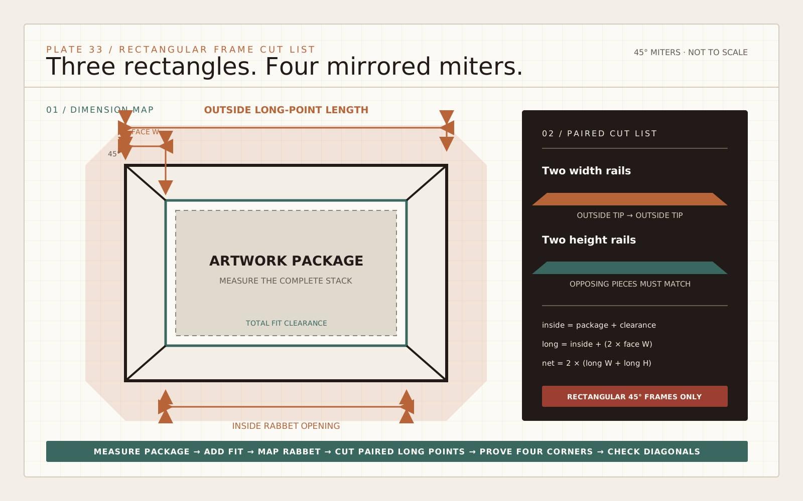
Name the package, rabbet and outside rectangles
A rectangular picture frame contains three related sizes. The package is the artwork, mat, glazing and backing that must fit. The rabbet opening is the recessed seat that receives that package. The outside rectangle runs to the long points of the four 45-degree miters. Confusing any two of these dimensions produces a frame that is predictably wrong.
Measure the assembled package, not a nominal print size. A window mat may surround an 8-by-10 image while the package itself is much larger. Measure width, height and thickness at several points. Confirm that the moulding rabbet is deep enough for the complete stack and the chosen retainers; this calculator handles plan dimensions, not rabbet depth.
Enter total fit clearance across each dimension, not clearance per side. The calculator adds that total once to package width and once to package height. Logan's Pro Saw instructions use an additional 1/8 inch in their example to let frame material fit, but fit allowance depends on the package, environment and framing method. Treat the entered value as an explicit design decision.
Convert inside size to long-point length
For a square rectangular frame with four true 45-degree miters, first calculate inside rabbet size: package dimension plus total fit clearance. Then calculate each outside long-point length: inside rabbet dimension plus twice the moulding face width.
inside width  = package width  + total fit clearance
inside height = package height + total fit clearance
outside width piece  = inside width  + (2 x moulding face width)
outside height piece = inside height + (2 x moulding face width)
You need two pieces at the outside width length and two at the outside height length. A package measuring 8 by 10 inches, with 1/8 inch total fit clearance and a 2-inch moulding face, produces an inside rabbet of 8-1/8 by 10-1/8 inches. The corresponding long-point pieces are two at 12-1/8 inches and two at 14-1/8 inches.
The relationship is geometry, not a saw calibration. It remains correct only when the frame is rectangular, opposing pieces match and every corner closes at 90 degrees. Multi-sided, compound, canted or intentionally non-square frames need different geometry.
Measure the working face width
On the back of the moulding, locate the inside rabbet corner: the point that defines the package opening. Measure square across the frame face from that inside corner to the outside edge. That is the working face width used in the formula. Do not substitute the total back width if a profile, liner or reverse slope changes the relationship.
Measure several points along real stock. Extrusions can be consistent, while wood moulding can vary through milling, sanding or finish build. If the profile is irregular, make a full-size cross-section tracing and mark the inside and outside miter points. The same two points must govern both the calculation and the stop setup.
Also inspect the rabbet lip. A fragile, undercut or heavily ornamented profile may not sit securely against an ordinary fence. Use a manufacturer-approved auxiliary fence, sacrificial support or dedicated framing saw system that fully supports the profile without moving hands toward the blade.
| Dimension | Measured between | Controls |
|---|---|---|
| Package width and height | Edges of the complete artwork stack | Minimum rabbet opening |
| Total fit clearance | Extra space across each full dimension | Handling and seasonal fit |
| Inside rabbet size | Opposing inside miter corners | Finished frame size at the package seat |
| Moulding face width | Inside rabbet corner to outside edge | Long-point extension at both ends |
| Outside long-point length | Two outside miter tips on one rail | Stop position for each pair |
Turn the result into paired cuts
Label the two width rails W1 and W2 and the two height rails H1 and H2. The calculator reports finished long-point lengths, so the dimension runs from outside tip to outside tip. Mark the rabbet side and finished face on every piece before cutting; mirrored miters are easier to recognize when orientation is visible.
Cut the longer pair first. Logan's framing guide recommends this sequence because a mistaken long part may still be recoverable as a shorter one. Establish the first clean 45-degree end, then place the correct reference point against a secure stop for the second cut. Do not trap a loose offcut between a stop and the blade; use the safe repetitive-cut arrangement described by the saw manufacturer.
After cutting the first rail, place it back-to-back with its mate and compare long points directly. Opposing rails must match each other for a square frame. A perfect calculated number cannot compensate for unequal pairs.
Calibrate with a four-corner proof
A scale that reads 45 degrees does not prove the finished joint. Make four test pieces from the actual profile or stable scrap, using the intended fence, stop and blade. Dry-assemble all four corners on a flat surface. A small angular error can look acceptable in one joint but multiply around the rectangle.
If all four corners form a gap pattern, correct the angle setup according to the machine manual and repeat the proof. If one pair is long or short, check stop position and debris. If the frame rocks, inspect profile support, stock twist and whether the face or back was registered consistently. Clean the fence and stop before every batch; a chip behind a rail changes length and angle.
OSHA identifies hand proximity to the blade as a primary miter-saw hazard and calls for guarding, sharp blades, eye and face protection and safe hand distance. The exact saw manual governs clamping, support, slide motion, minimum workpiece size and no-hands zones. A calculator never authorizes a cut that the tool cannot support safely.
Estimate stock without hiding waste
The net finished perimeter equals twice the width-piece long-point length plus twice the height-piece long-point length. Multiply by frame quantity, then apply the entered stock allowance. The calculator reports both inches and feet so a purchasing estimate stays traceable.
Allowance is not the same as kerf. The four reported rail lengths are finished dimensions. Raw stock also has to provide blade kerfs, end-trimming room and a safe way to hold each cut. A percentage allowance can cover ordinary defects and setup loss for planning, but short remnants, matched grain, repeating ornament and corner-pattern alignment require a drawn board-by-board layout.
For expensive or repeating moulding, lay transparent corner templates over the stock and mark the exact sequence. Keep adjacent corners close in grain and color where possible. Confirm that available stick lengths can yield the required long rails; enough total linear footage does not guarantee that any single piece is long enough.
Dry-fit, measure diagonals and preserve the evidence
- Place all four rails face-down on a verified flat surface.
- Bring the miters together without forcing them closed.
- Compare opposing rail lengths and measure both outside diagonals.
- Check the rabbet opening against a same-size dummy package, not valuable artwork.
- Verify corner reinforcement, clamp access and finish protection.
- Mark joint order and keep the calibrated test frame beside the setup.
Equal diagonals are evidence that a rectangular assembly is square, but they do not prove every miter face is straight or every rail is untwisted. Read the corner contact and flatness as well. If a package binds, identify whether the error is clearance, a proud fastener, finish buildup or an out-of-square frame before trimming the artwork.
Once the dry fit passes, use an adhesive and reinforcement method suitable for the moulding and frame duty. Follow the adhesive's open, clamp and cure schedule. The numerical output has done its job when every finished dimension can be checked against a labeled physical part.